Guide
CC1101 on an FT232H: a 433 MHz scanner in the terminal
Published · Updated · Discuss on Hacker News
Our gate remotes send on 433 MHz, and I wanted to see what those signals looked like. A cheap AliExpress copy remote couldn’t learn them. So I put a CC1101 radio module on a CJMCU-232H, an FT232H board that plugs straight into the laptop. Six jumper wires and a Python script: no microcontroller to flash, nothing to solder.
This setup and test was just to prove that the FTDI board could be connected to the 433 MHz board (bought from AliExpress), and that together they could scan and visualise simple signals from a bootleg remote.
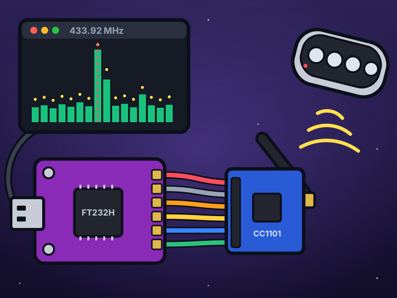
The rig, drawn: the FT232H board, six wires, the CC1101 and its antenna.
What you need
Section titled “What you need”- A CC1101 433 MHz module and its antenna. Mine is an E07-M1101D (Ebyte’s board layout, with an SMA socket), about AU$3.40 on AliExpress.
- A CJMCU-232H: a purple board with an FTDI FT232H chip and a USB-A plug.
- A breadboard, 4 male-female jumper wires and 2 female-female ones.
- Linux with Python 3. The script uses pyftdi.
- Something that sends on 433 MHz to test with. I used the copy remote.
The CC1101 talks SPI. A plain USB-serial stick (CP2102, CH340) only does serial, so it can’t drive it. The FT232H does SPI from USB, so Python on the laptop talks to the radio directly. The usual way is an ESP32 running ESPHome, which means building and flashing firmware every time you change something.
Step 1: Download the files
Section titled “Step 1: Download the files”- rf-scan-ft232h.py: the scanner
- keeloq-capture-ft232h.py: sets up the CC1101 and samples its data. The scanner uses it, and on its own it captures KeeLoq remote presses
- keeloq-check.py: the KeeLoq decoder both of them use
- 70-ftdi-ft232h.rules: a udev rule so your user can open the board
All four are MIT licensed. Keep the three scripts in one folder.
mkdir -p ~/cc1101 && cd ~/cc1101curl -O https://blog.jacq.cc/cc1101-scanner/rf-scan-ft232h.py \ -O https://blog.jacq.cc/cc1101-scanner/keeloq-capture-ft232h.py \ -O https://blog.jacq.cc/cc1101-scanner/keeloq-check.py \ -O https://blog.jacq.cc/cc1101-scanner/70-ftdi-ft232h.rulesStep 2: Install pyftdi and the udev rule
Section titled “Step 2: Install pyftdi and the udev rule”python3 -m venv .venv.venv/bin/pip install pyftdisudo install -m 644 70-ftdi-ft232h.rules /etc/udev/rules.d/sudo udevadm control --reload.venv/bin/python rf-scan-ft232h.py --self-testThe rule tags the FT232H (USB ID 0403:6014) with uaccess, so the logged-in user can open it: no sudo to run the scanner. Plug the board in after reloading the rules, or unplug it and plug it in again. --self-test needs no hardware: it decodes synthetic noisy presses, and a real frame from my copy remote.
Step 3: Wire it
Section titled “Step 3: Wire it”The CC1101’s header prints only pins 1, 2, 7 and 8. Pin 1 is the square pad, the odd pins run along the board’s edge, and the even pins sit on the inside.
| CC1101 pin | Name | CJMCU-232H |
|---|---|---|
| 1 | GND |
GND on the 4-pin header |
| 2 | VCC |
+3.3V on the 4-pin header. Never +5V, and not VCORE |
| 4 | CSN |
AD3 |
| 5 | SCK |
AD0 |
| 6 | MOSI |
AD1 |
| 7 | MISO / GDO1 |
AD2 |
| 3, 8 | GDO0, GDO2 |
not connected |
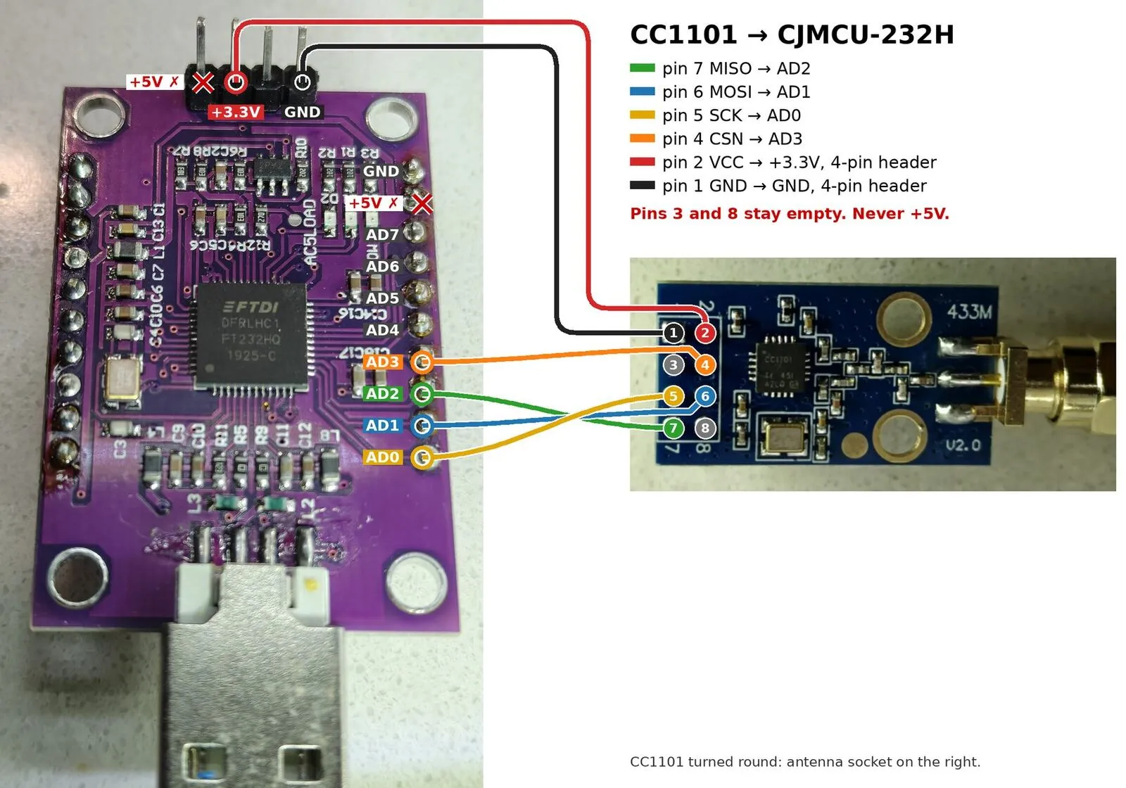
Six wires. The CJMCU-232H prints its pin names only on the back, so they’re drawn in here.
The CJMCU-232H goes on the breadboard. The CC1101 stays off it: its 2 × 4 header would short its pins in pairs along the breadboard’s rows. So the signal wires go male end into the breadboard beside the AD pins, female end onto the CC1101. The power pair goes female to female, straight onto the 4-pin header.
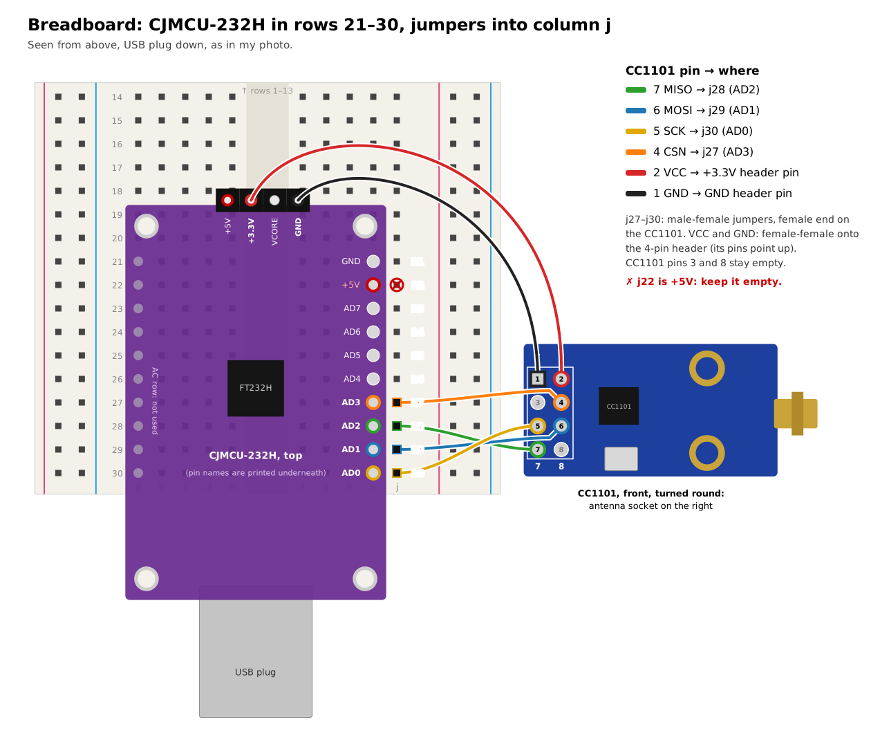
My layout: the board’s AD row in rows 21 to 30, the jumpers in column j beside it.
- Screw the antenna onto the CC1101.
- Power first, with female-female wires: CC1101 pin 1 to
GNDand pin 2 to+3.3Von the 4-pin header. - Signals, with male-female wires: pin 4 to
AD3, pin 7 toAD2, pin 6 toAD1, pin 5 toAD0. - Leave
+5Vand CC1101 pins 3 and 8 empty.
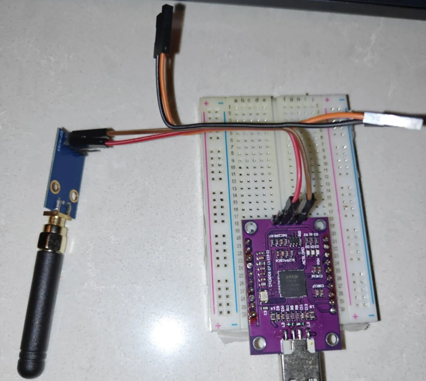
Power first: red from pin 2 to +3.3V, brown from pin 1 to GND.
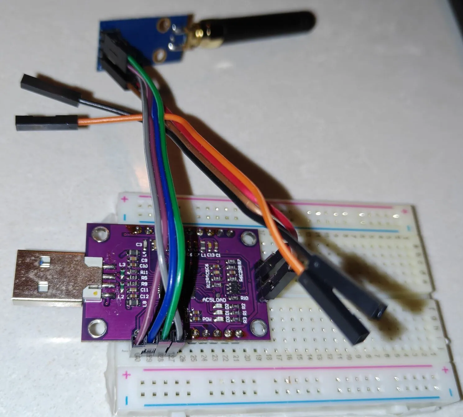
All six wired. The loose black and orange jumpers aren’t part of it.
The USB plug hangs off the end of the breadboard. A short USB extension cable helps.
Step 4: Run it
Section titled “Step 4: Run it”.venv/bin/python rf-scan-ft232h.pyUse a terminal window at least 60 × 20. Before the screen starts, the script checks the radio: it reads the chip’s version (mine says 0x14), writes its settings and reads them back, and checks it’s receiving. If something fails, it names the wires to check. “No CC1101 answers” means power, SCK, MISO or CSN. Settings that read back wrong mean MOSI.
It only receives. It never transmits.
There are two screens, and Tab switches between them.
| Key | Sweep | Listen |
|---|---|---|
| Tab | listen at the marker (Enter too) | back to the sweep |
| ← → | move the marker one column | tune ±10 kHz |
[ ] |
move the marker 10 columns | tune ±100 kHz |
p |
marker to the strongest signal | |
z x |
zoom in or out around the marker | |
b |
next band | |
c |
clear | clear |
q |
quit and print a summary | quit and print a summary |
Other options:
--band 315starts on another band:433(the default, 432 to 436 MHz),315,300-348,387-464,779-928,all, or anySTART-STOPin MHz.--listen 433.92starts on the listen screen.--textprints plain lines instead of the screen, and--seconds 30stops it by itself.--replay /tmp/rf-listen.logdecodes a saved log instead of the radio.
The CC1101 only tunes 300 to 348, 387 to 464 and 779 to 928 MHz. A 433 MHz module and antenna hear only strong signals in the other bands.
Step 5: Sweep
Section titled “Step 5: Sweep”The sweep steps across the band and reads the signal strength (RSSI) at each step. It shows bars with peak hold (yellow dots), a waterfall of past sweeps underneath (newest at the top), and the strongest signals seen along the bottom.
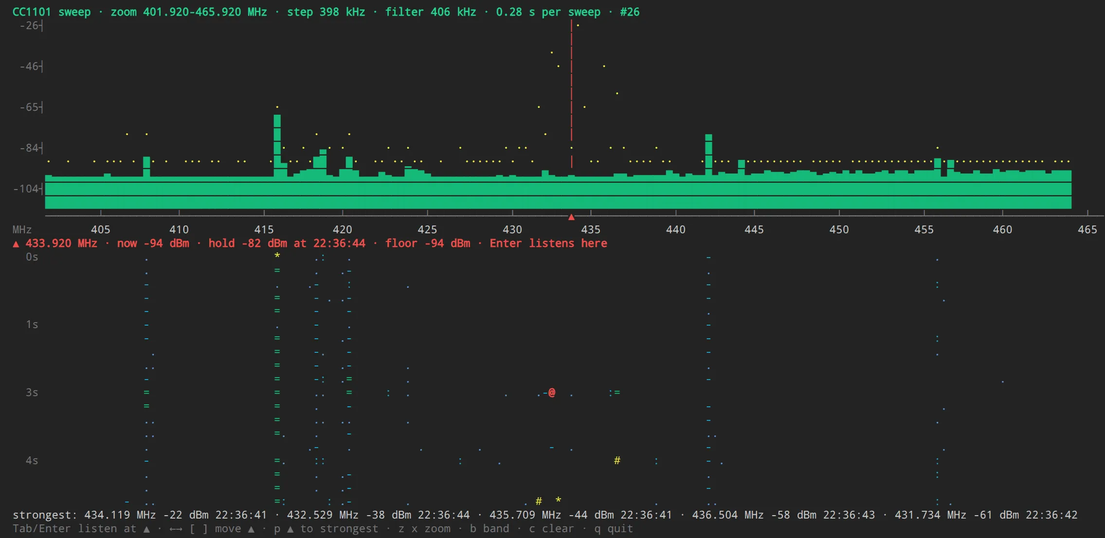
Zoomed out to 402 to 466 MHz, with a remote pressed near 434 MHz.
- The 433 band sweeps in 0.16 s. All three bands take 0.6 s.
- The noise floor here is about −90 dBm.
- Steady signals sit near 408, 416, 418 to 420, 442 and 456 MHz, pressed or not. The one near 416 MHz is the strongest, at about −65 dBm.
- A press near 434 MHz reads up to −22 dBm. Close to the antenna, it spills into the steps around it, from 431.7 to 436.5 MHz.
- On all bands, two more peaks show up at 782 and 883 MHz. Both are in mobile phone tower bands.
Step 6: Listen
Section titled “Step 6: Listen”Put the marker on a signal and press Tab. The listen screen stays on that one frequency and records what the CC1101 demodulates. It shows the signal strength over the last minutes, the last frame’s pulses and bits, and every code heard more than once, with a guess at the protocol. The timings go to /tmp/rf-listen.log.
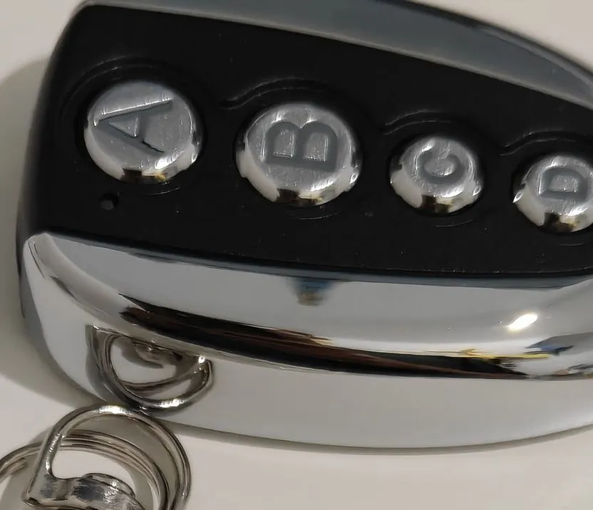
The copy remote. It sends a fixed code: the same bits on every press.
Inside is a board marked 520B V2.1: four buttons (K1 to K4), a 433 MHz SAW resonator (R433) and a 12 V 27A battery. The chip is an FMD FT60E021, a general-purpose 8-bit microcontroller, not a dedicated remote encoder, so the code it sends comes from its firmware. The gate remotes have a KeeLoq encoder chip instead, the HCS300.
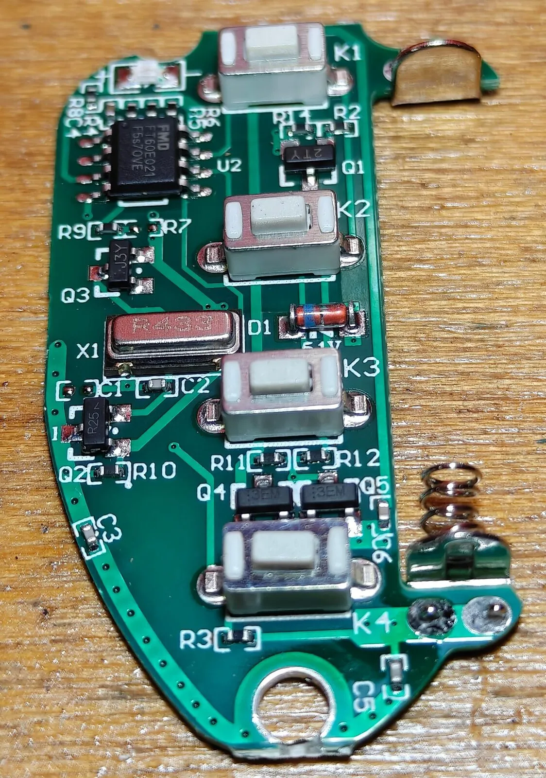
The board: the chip (U2), the resonator (X1) and the four buttons.
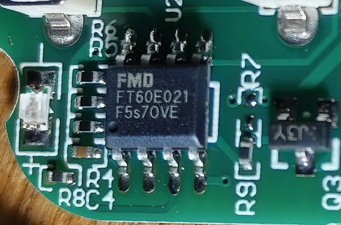
The chip: an FMD FT60E021 microcontroller.
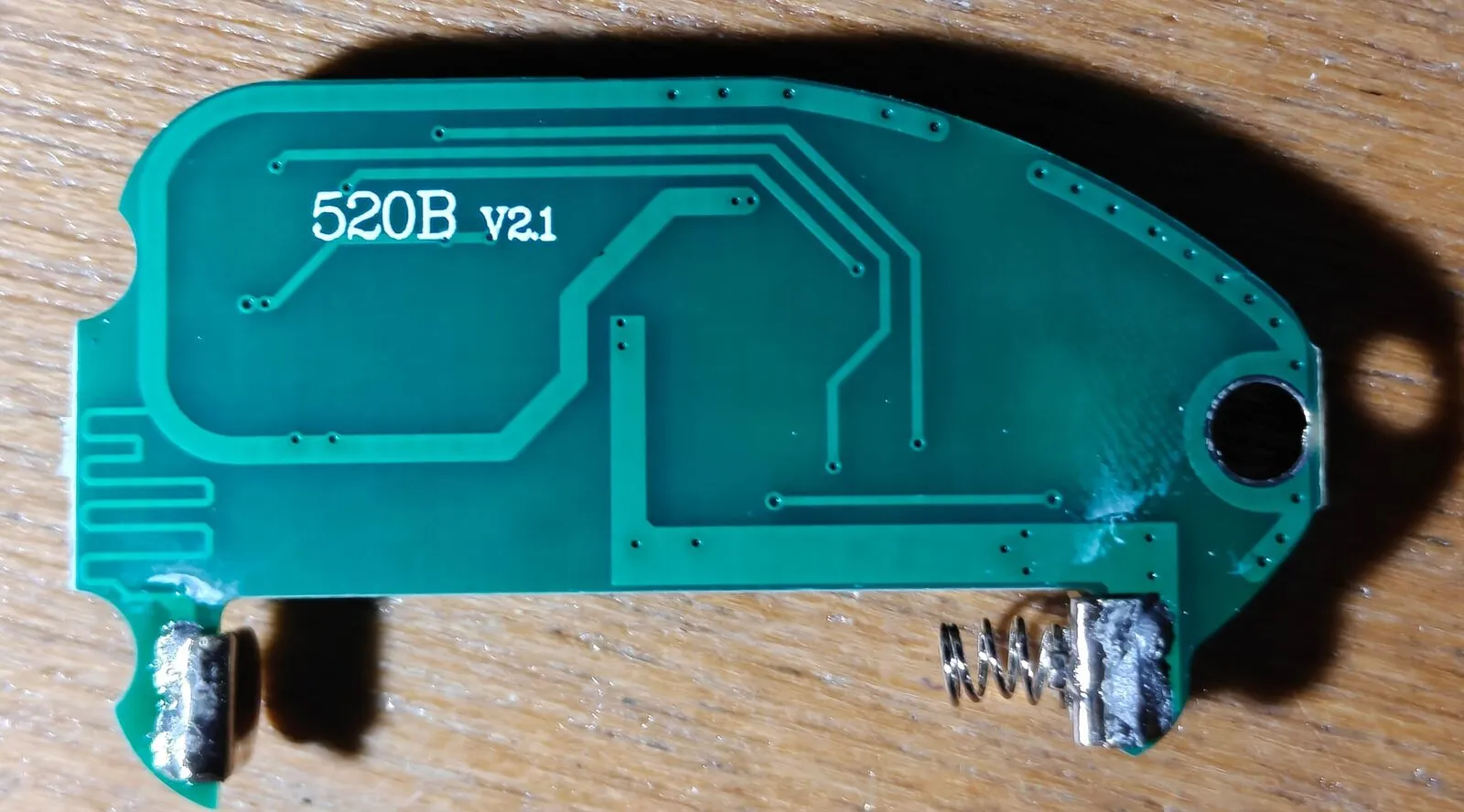
The back. The antenna is a copper trace printed on the board.
The copy remote’s specs, its parts and its instruction sheet are on its device page: AliExpress 433 MHz copy remote.
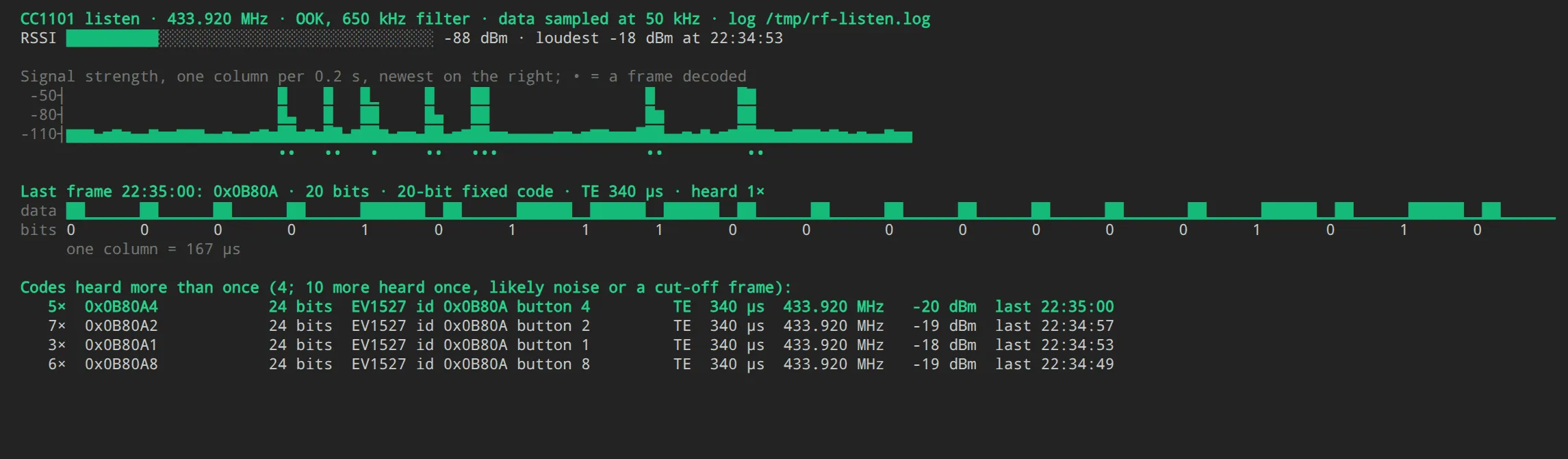
All four buttons of the copy remote, one short press each.
The copy remote sends EV1527-style codes: 24 bits, a 20-bit ID (0x0B80A) and 4 button bits. Its buttons send 0x0B80A1, 0x0B80A2, 0x0B80A4 and 0x0B80A8. The shortest pulse (TE) is 340 µs. The presses came in at −18 to −20 dBm, against a floor of −88 dBm. A remote repeats its code while the button is down, so each short press gave 3 to 7 frames.
Holding the buttons down fills the list with shorter codes too, 12 to 22 bits long, like 0x80A4 and 0x0B80. They’re pieces of the real codes that noise cut short. Only the 24-bit rows are real.
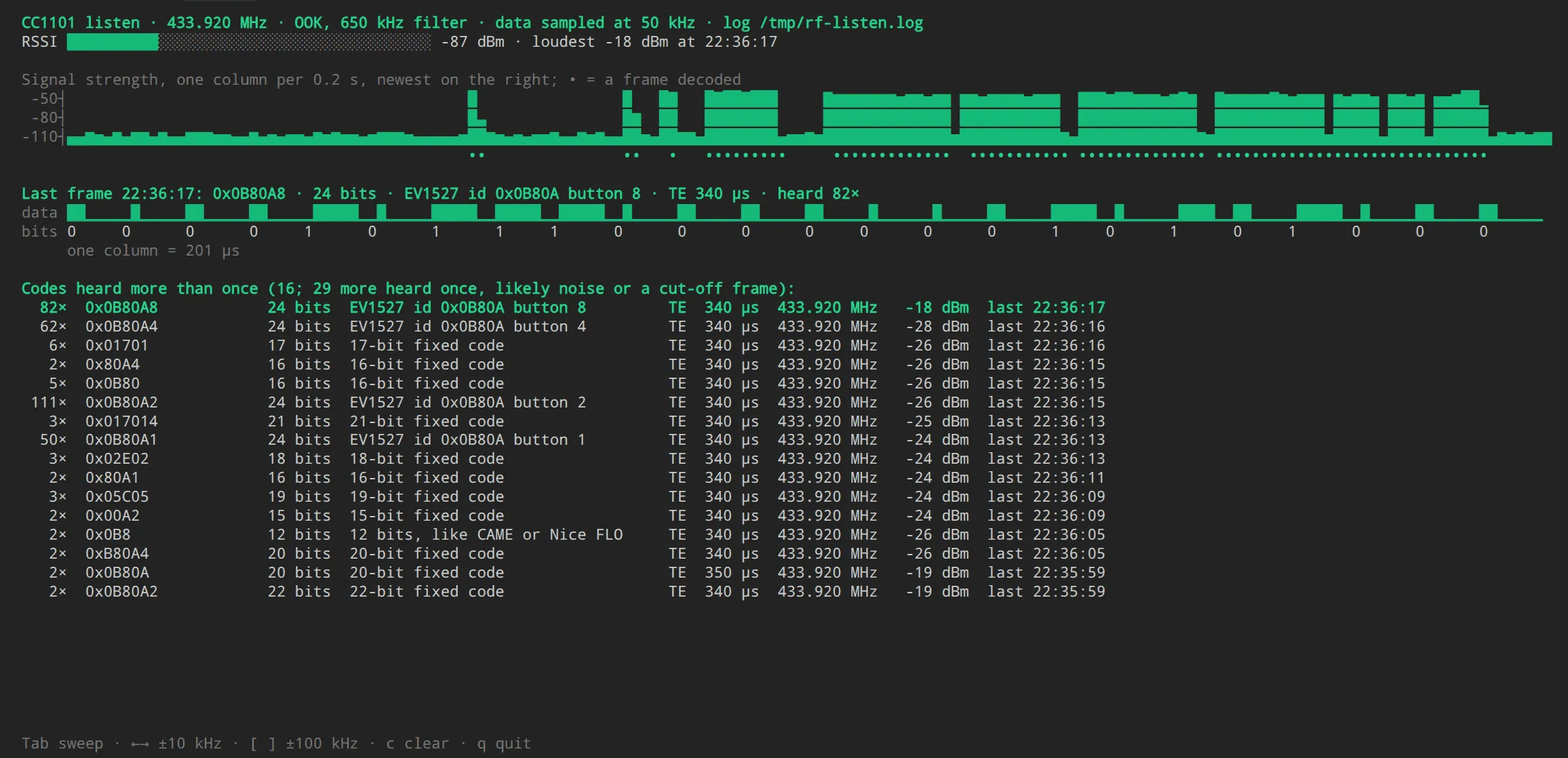
Buttons held down: the four real codes, and pieces of them.
How it works
Section titled “How it works”The script sets the CC1101 up as an OOK receiver on 433.92 MHz, with Flipper Zero’s AM650 settings: a 650 kHz filter and no packet handling. The chip puts the demodulated data on its GDO1 pin. On this module GDO1 shares a pin with MISO: while CSN is high, nobody is talking to the chip and MISO carries the data.
The FT232H is already in SPI mode to talk to the radio, and an SPI read clocks bits in at a steady rate. So the script opens a second SPI port on a chip-select pin that isn’t wired, AD4. Reading from it leaves CSN high and clocks MISO in at 50 kHz: a sample every 20 µs, about 17 of them per 340 µs pulse. A thread keeps the USB reads back to back, and the decoder turns runs of ones and zeros into pulse lengths.
When the radio is idle, its output on my rig is mostly high with short dips. That noise often runs straight into the start of a frame and swallows the first bit’s high pulse. Every frame of the copy remote came out 23 bits long instead of 24. The fix: read that bit from its low pulse alone. In EV1527 a 1 is a long high and a short low, and a 0 is a short high and a long low.
For the sweep, the script tunes to each step, waits 1.2 ms for the chip to calibrate and settle, and reads its RSSI register. The filter is set as wide as the step, so a sweep leaves no gaps between steps.
How it turned out
Section titled “How it turned out”The test was quite successful, and the TUI proved quite handy for learning and seeing what these remotes can output.
Next: the gate remotes
Section titled “Next: the gate remotes”The next project builds on this one: scanning the Richmond gate remotes to see what they output and what that looks like. They’re the same remotes that open our garage through a GE-RCV1. Inside each one is a Microchip HCS300, a KeeLoq rolling-code chip. A rolling-code remote shouldn’t send the same thing twice. Each press is a 66-bit frame: the remote’s serial number and buttons in the clear, and a 32-bit encrypted part that holds a counter, which goes up on every press.
I’ll also try to match the signal with known OEM keys: KeeLoq’s manufacturer keys, which each remote’s own key is made from. If I find a matching key, I won’t publish what the key is, only that I was able to find it, whether from an OEM list or by brute force.
I’m quite excited about this next part of the experiment: it’s becoming quite a little sleuthing puzzle to solve.
Sources
Section titled “Sources”- TI CC1101 datasheet (PDF): the registers,
GDO1on theSOpin whileCSNis high, and RSSI to dBm - Ebyte E07-M1101D-SMA user manual (PDF): the module’s pins, and its 1.8 to 3.6 V supply
- pyftdi: SPI on the FT232H, and its installation page for the udev rule
- Flipper Zero firmware,
cc1101_configs.c: the AM650 register settings
Questions or comments? Discuss on Hacker News.
Change history
- : Step 6: photos of the copy remote's insides, the board and its FT60E021 chip, and a link to its device page with the specs and the full teardown.
- : First published.
This guide as plain Markdown, for LLMs and scripts: cc1101-433mhz-scanner-ft232h.md. All posts: API and Markdown.
Text, photos and drawings: CC BY 4.0. Code: MIT. Share and adapt them, crediting HomeLab Series (blog.jacq.cc). Licence and privacy