Guide
GE-RCV1: open the garage with the gate remote
Published · Updated
Our gate remotes have spare buttons. A small 433 MHz receiver at the garage motor turns one of them into a garage opener, so there’s one remote on the key ring instead of two.
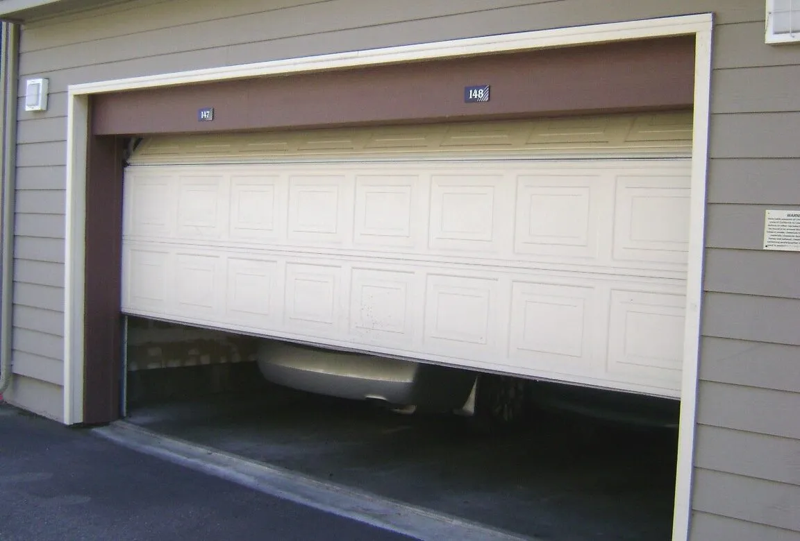
Not our garage: any opener with a push-button input works the same way. Photo: Oleg Alexandrov, public domain, via Wikimedia Commons.

What you need
Section titled “What you need”| Part | Notes |
|---|---|
GE-RCV1 receiver, 1-channel (label GE-RCV1 AC-DC-12V-24V, code SC2504004) |
433.92 MHz. Sold as an add-on receiver for Richmond gate kits |
| A gate remote with a spare button | Mine came with a Richmond GTR156 sliding gate |
| A garage motor with a push-button input | A Steel-line SD1200 here. Most openers have one: it’s where a wired wall button goes |
| Multimeter, small flat screwdriver, a short insulated wire | |
| Optional: a 12 V DC supply | To bench-test the receiver before it goes near the motor |
About 45 minutes, including the bench test.
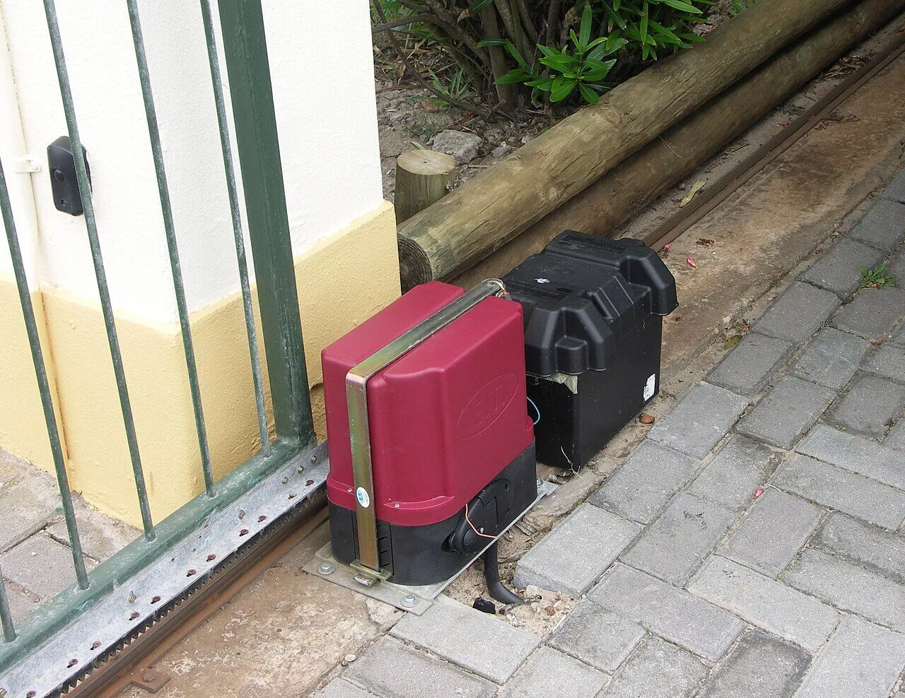
A sliding gate motor like the one whose remotes this uses (this one isn’t a Richmond). Photo: NJR ZA, CC BY-SA 3.0, via Wikimedia Commons.

How it works
Section titled “How it works”A garage motor’s push-button input is a pair of terminals. Shorting them for under a second does the same as pressing a wall button: open, stop, close, stop, in turn. The receiver has a relay that closes for a moment when it hears a paired remote button. Put that relay across the push-button terminals, and the remote button becomes a wall button.
Step 1: Test the motor’s push-button input
Section titled “Step 1: Test the motor’s push-button input”The SD1200’s terminal block reads Receiver | Receiver | com | +24VDC (installation manual, page 7).
- Clear the door’s path: it will move.
- Touch an insulated wire across the two
Receiverterminals for under a second, then take it away. - The door starts. Each short moves it to the next step: open, stop, close, stop.
On my SD1200 this worked first time.
Step 2: Find the common side of the input
Section titled “Step 2: Find the common side of the input”The receiver’s output isn’t a floating contact (step 3 shows why): one side of it is the receiver’s own power wire. So in step 4 one Receiver terminal gets joined to com. That’s only safe if the motor already joins them inside.
- Switch the motor off at the wall.
- Multimeter on continuity. Test
comagainst eachReceiverterminal. One should beep (close to 0 Ω): that’s the common side. Mark it. - Switch the motor on. DC volts between
comand+24VDCshould read about 24 V. That’s the receiver’s power.
If neither Receiver terminal beeps to com, don’t use the wiring in step 4. Make the receiver’s output a dry contact first (below).
Step 3: Know the receiver’s wires
Section titled “Step 3: Know the receiver’s wires”The closest manual is for Richmond’s GTR197, the 4-channel version. That one has a 2-core power cable and a 5-core output cable. The 1-channel unit has 3 wires (red, black, yellow) plus the antenna, so the manual’s wire colours don’t apply. I opened it to see where they go.
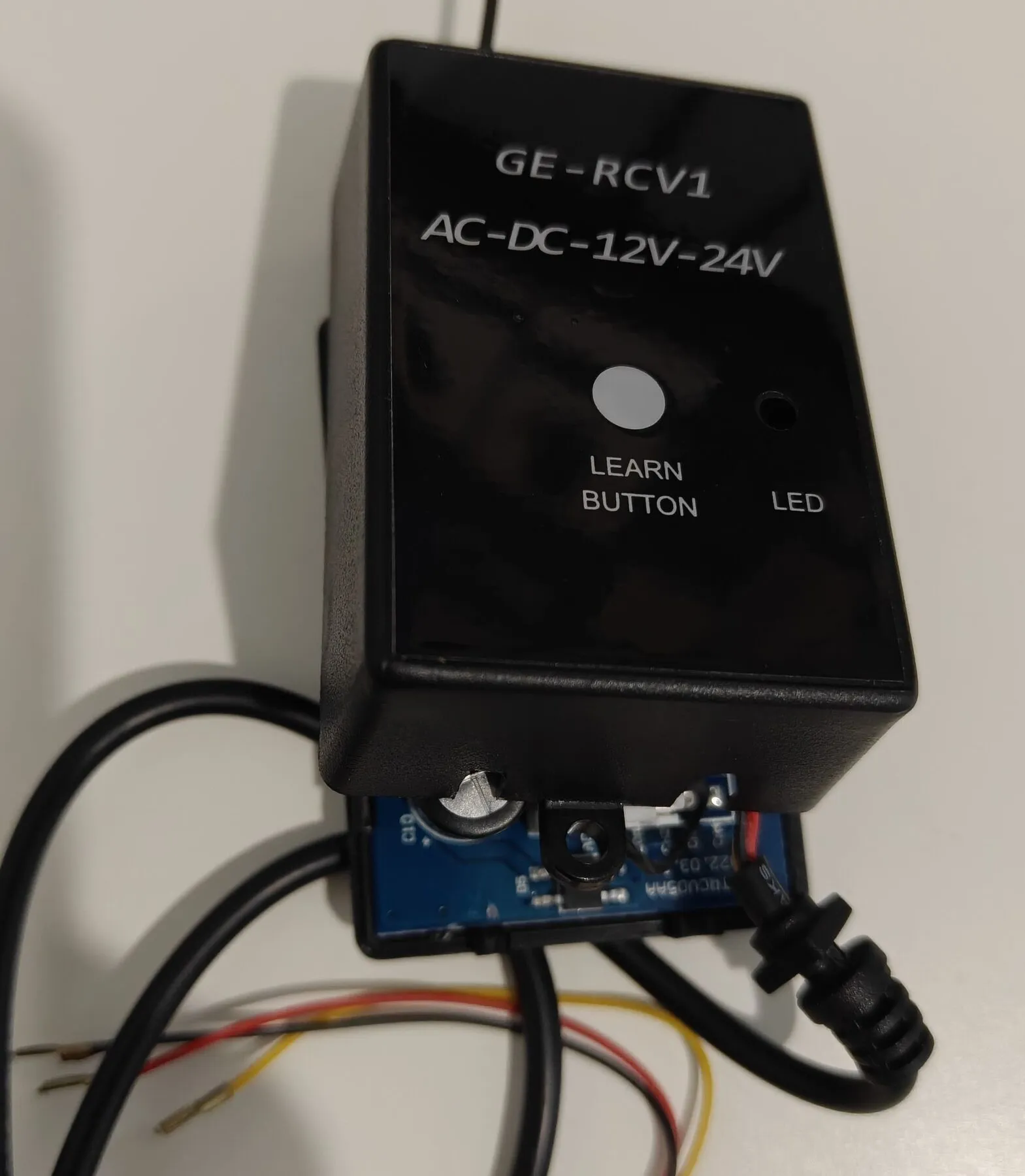
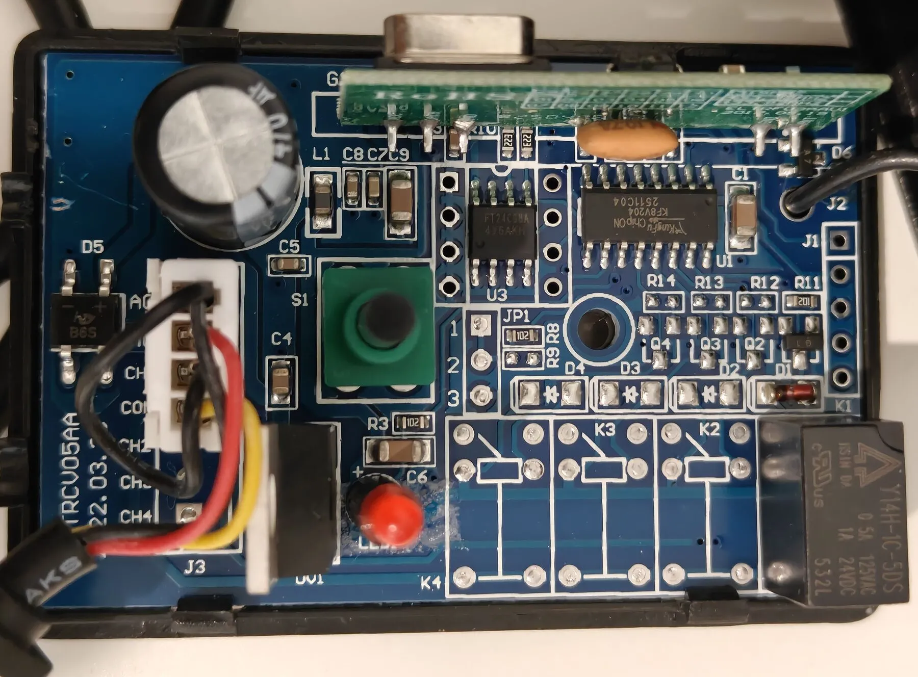
Inside there’s one relay, K1 (a Y14H-1C-5DS). The spots for K2 to K4 are empty. The wires plug into connector J3, printed AC, AC, CH1, COM, CH2, CH3, CH4:
| J3 pin | Wire |
|---|---|
AC (1) |
black, plus a short black jumper to CH1 |
AC (2) |
red |
CH1 |
the other end of that jumper (inside the case only) |
COM |
yellow |
CH2 to CH4 |
nothing |
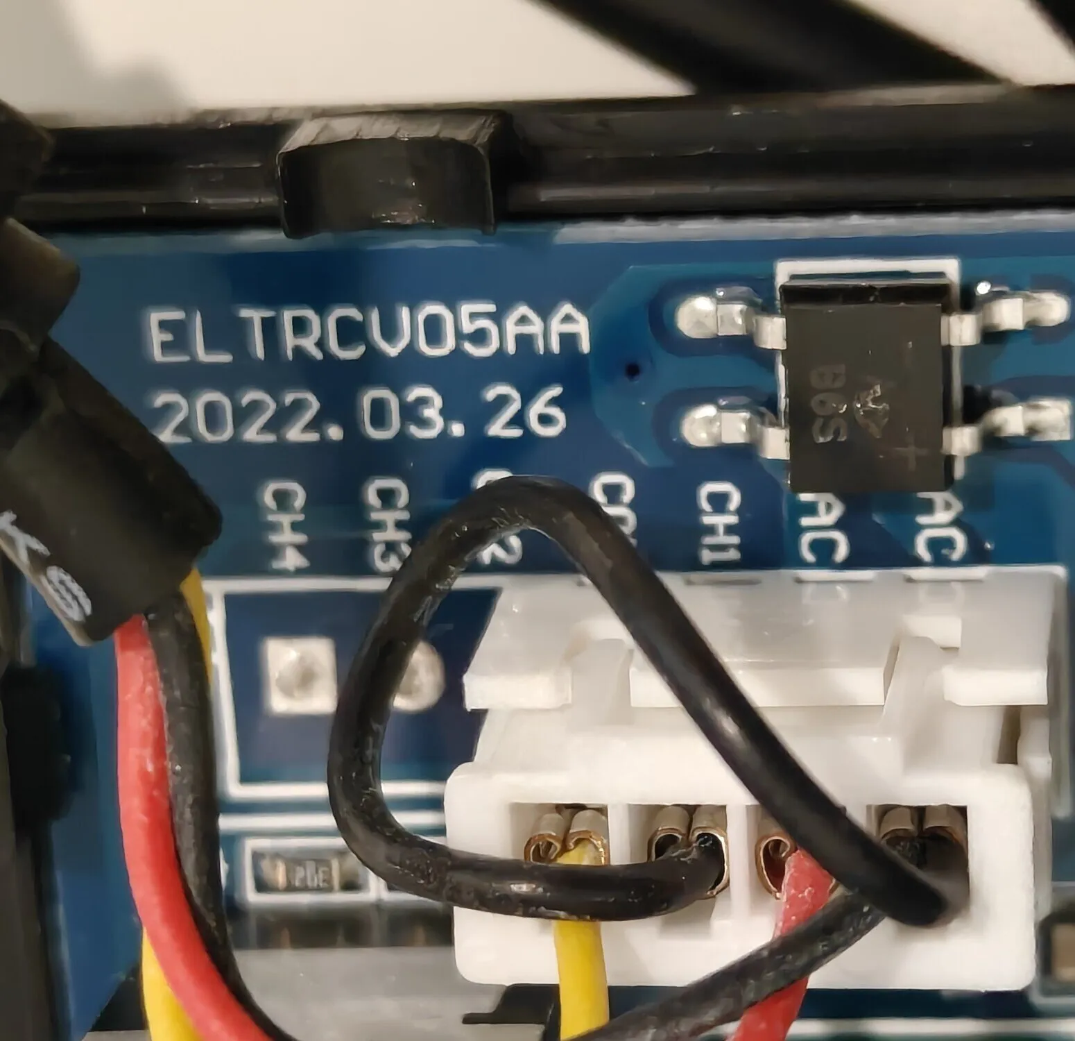
What that means:
- Power goes in on red and black. Both
ACpins feed a bridge rectifier (the B6S next to J3), so 12 to 24 V, AC or DC, either way round, works. - The output is the relay switching
COMtoCH1, and the jumper tiesCH1toAC(1), the black wire. So the output is yellow to black: open at rest, shorted while a paired button is pressed. - Polarity matters for the output. Black is both a power wire and one side of the output, so black must go to the motor’s common side.
Step 4: Wire it to the motor
Section titled “Step 4: Wire it to the motor”Motor off at the wall first.
| GE-RCV1 wire | SD1200 terminal |
|---|---|
| red | +24VDC |
| black | com, and the Receiver terminal that beeped to com in step 2 |
| yellow | the other Receiver terminal |
When the relay closes, yellow joins black, which shorts the two Receiver terminals: the same as the wire in step 1. Mine is wired exactly like this, and it works.
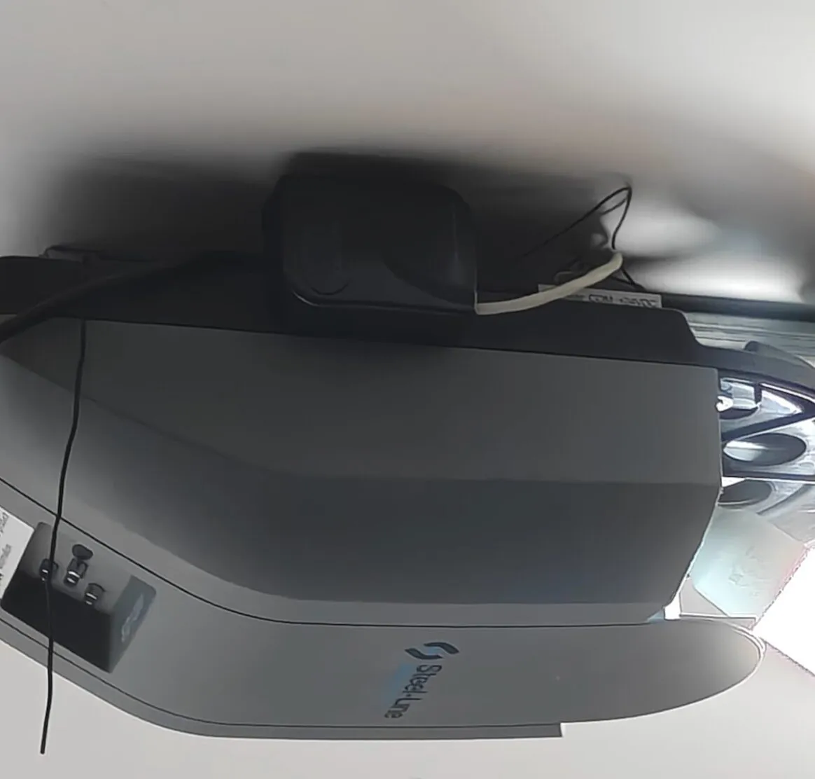
Mine, wired and working: the GE-RCV1 (the black box on top) on the Steel-line SD1200.
Step 5: Pair the spare remote button
Section titled “Step 5: Pair the spare remote button”These are the GTR197 manual’s steps (page 2). Pairing the 1-channel unit worked for me.
- Press LEARN on the receiver once. The LED stays on.
- Press the spare remote button twice. The LED flashes 2 or 3 times, then goes off: paired.
- Press the button again. The garage door starts.
Optional: bench-test it first
Section titled “Optional: bench-test it first”Power the receiver from a 12 V DC supply on the bench (red and black, either way round) and pair the remote as in step 5. Put the multimeter on continuity between yellow and black: it beeps briefly on each press. Now nothing can surprise you at the motor.
Want a dry contact?
Section titled “Want a dry contact?”Take the short jumper between AC (1) and CH1 out of J3, and bring CH1 out as a fourth wire. Yellow to that new wire is then an isolated contact, and it can go across any push-button input, whichever way round.
Next: Home Assistant control
Section titled “Next: Home Assistant control”Not built yet. The push-button input happily takes a second trigger in parallel with the receiver. The parts are here: a Seeed XIAO ESP32-C6 and a 3 V relay module (Songle SRD-03VDC-SL-C) for each motor. The C6 has a Zigbee radio, so it joins Home Assistant over Zigbee, like the door’s contact sensor already does.
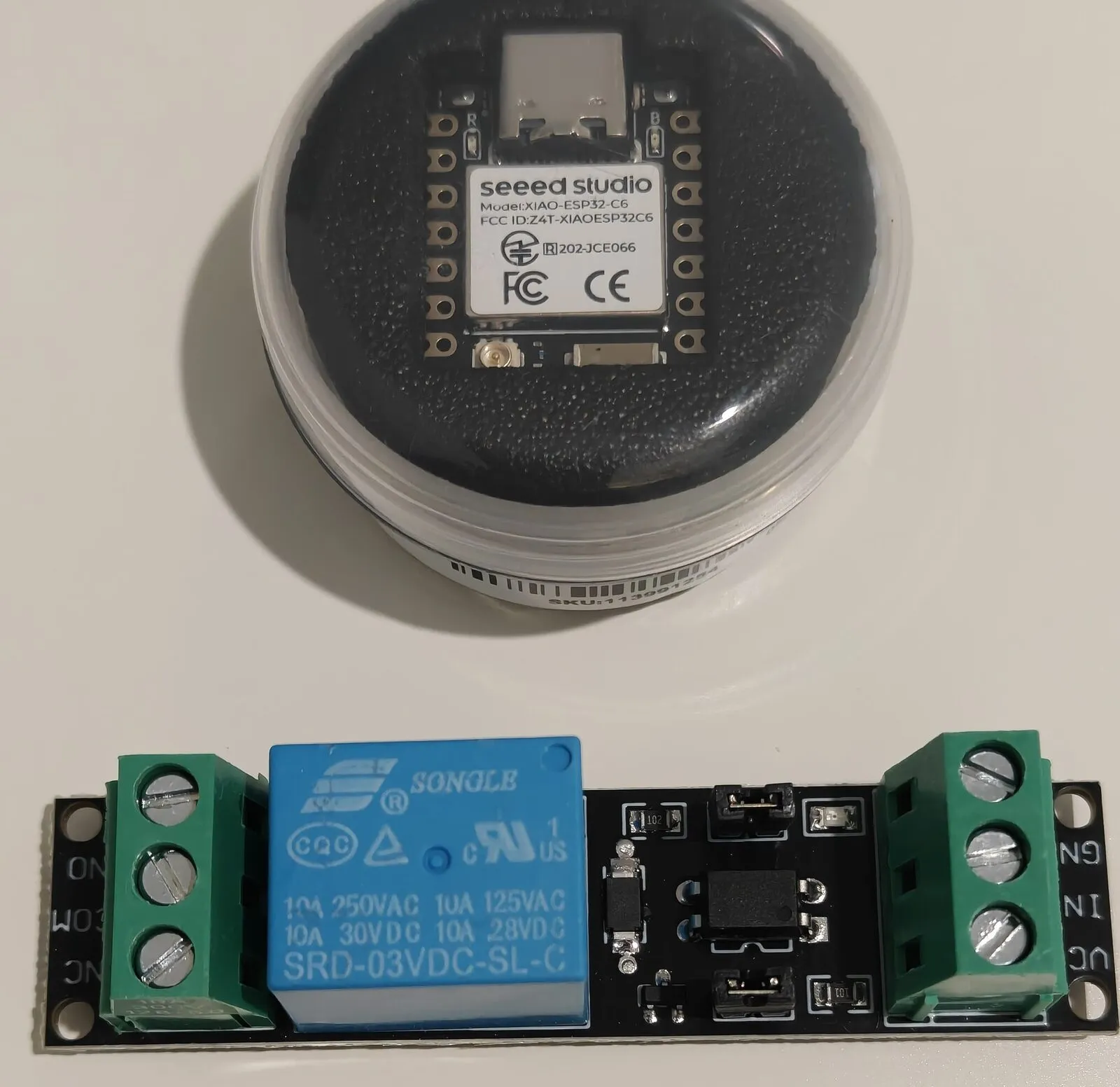
The parts for the next step: the XIAO ESP32-C6 (still in its tub) and the 3 V relay module.
- A button in Home Assistant pulses the relay for about half a second.
- The relay must stay off while the ESP boots, so a reboot or power cut never moves the door: a pin with no boot role (D0 to D3 on the XIAO), and firmware that starts with the relay off.
- Door state comes from a Zigbee contact sensor, not the relay. One input does open, stop and close in turn, so the relay alone can’t know where the door is.
- Power from the motor: a 24 V to 5 V buck converter on the SD1200’s
+24VDCandcom. - The gate’s controller (Richmond GTR156) has a 15 V accessory output and two inputs: open/stop/close, or open only, which can never close the gate on someone. Its manual says changes inside the controller are for a licensed electrician.

Our gate’s Richmond GTR156 motor, enlarged from a wider photo, so it’s soft.
That gets its own guide once it’s built.
Manuals
Section titled “Manuals”- Steel-line SD1200 installation manual (PDF)
- Richmond GTR197 external receiver manual (PDF): the 4-channel receiver; its pairing steps work for the GE-RCV1
- Richmond GTR156 gate motor manual (PDF)
Change history
- : First published.