Guide
Use the Tello's GameSir T1d controller as a Linux gamepad
Published · Updated · Discuss on Hacker News
The GameSir T1d is the Bluetooth controller sold with the Ryze/DJI Tello drone. Try to pair it with a PC and nothing happens. It’s Bluetooth Low Energy only, and it speaks GameSir’s own GATT protocol instead of the HID profile real gamepads use. Linux, Windows, Android and SteamOS all ignore it, and GameSir says it’s Tello-only.
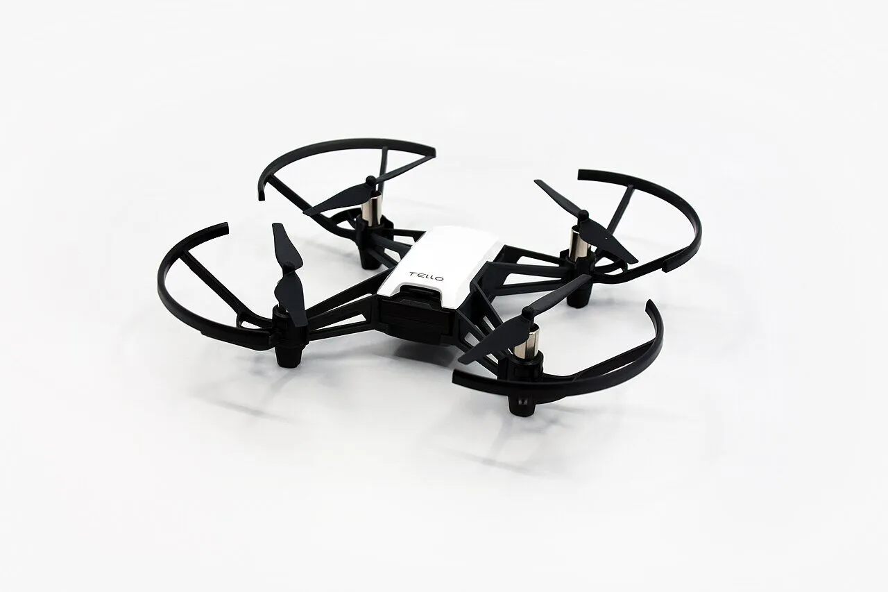
The Tello. Photo: SimonWaldherr, CC BY-SA 4.0, via Wikimedia Commons.

It still talks to a PC over BLE, without pairing. So a small bridge program can read its input reports and create a virtual Xbox 360 pad through Linux’s uinput. Steam, SDL and most Linux games then see an ordinary wired controller. No hardware change.
My kids have been using it for online games, and they’re happy with it. The Tello is long gone, but at least the controller didn’t end up in landfill.
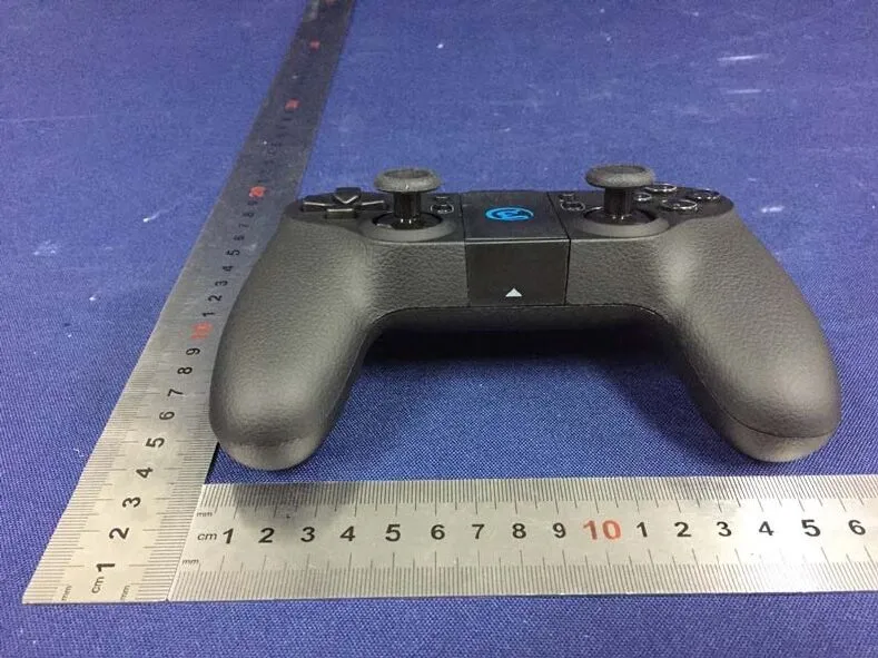
The T1d, with its phone clamp off. Photo: FCC filing 2AF9ST1D, external photos.
What you need
Section titled “What you need”-
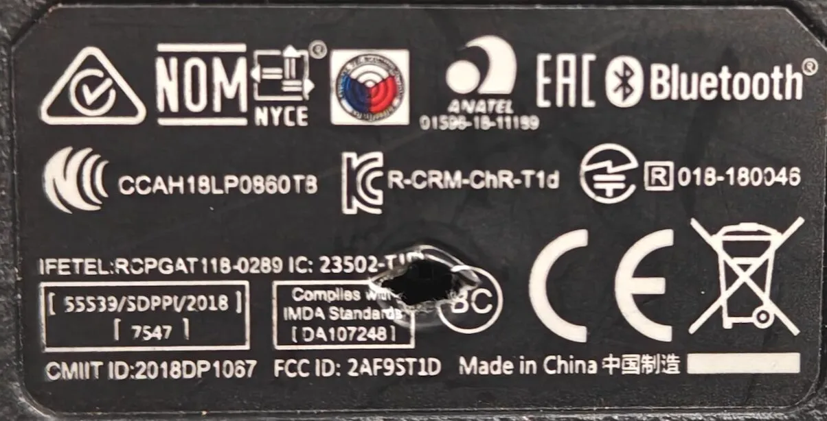
A GameSir T1d: the label on the back says
FCC ID: 2AF9ST1D. The T1s looks the same but is a different board, so this guide isn’t for it. -
A Linux PC with Bluetooth 4.0 or newer.
-
Python 3.
About 15 minutes.
Step 1: Download the files
Section titled “Step 1: Download the files”- t1d-bridge.py: the bridge
- 60-t1d-bridge-uinput.rules: a udev rule so your desktop user can create the virtual pad
- t1d-probe.py: optional, prints the controller’s GATT table and decoded input
All three are MIT licensed.
mkdir -p ~/t1d && cd ~/t1dcurl -O https://blog.jacq.cc/gamesir-t1d/t1d-bridge.py \ -O https://blog.jacq.cc/gamesir-t1d/60-t1d-bridge-uinput.rules \ -O https://blog.jacq.cc/gamesir-t1d/t1d-probe.pyStep 2: Install bleak and python-evdev
Section titled “Step 2: Install bleak and python-evdev”bleak talks BLE through BlueZ; python-evdev creates the virtual pad.
python3 -m venv ~/.venvs/t1d~/.venvs/t1d/bin/pip install bleak evdevStep 3: Let your user create a virtual gamepad
Section titled “Step 3: Let your user create a virtual gamepad”sudo install -m 644 60-t1d-bridge-uinput.rules /etc/udev/rules.d/sudo udevadm control --reload && sudo udevadm trigger --name-match=uinput~/.venvs/t1d/bin/python t1d-bridge.py --selftestThe rule tags /dev/uinput with uaccess, so the logged-in desktop user gets access to it: no sudo to run the bridge, no group change, no logging out. --selftest creates the virtual pad and moves it, with no controller needed.
Step 4: Calibrate the sticks, once
Section titled “Step 4: Calibrate the sticks, once”Turn the controller on: hold Power for 2 seconds, and the four LEDs blink while it waits for a connection. Then:
~/.venvs/t1d/bin/python t1d-bridge.py --calibrateFor 10 seconds, move both sticks slowly round their full circle and into every corner. The real range of each axis is saved in ~/.config/t1d-bridge/<MAC>.json. Skip this and a worn stick may not reach full travel (why).
Step 5: Run it
Section titled “Step 5: Run it”~/.venvs/t1d/bin/python t1d-bridge.py -vThen open any gamepad tester (evtest, Steam’s controller settings, KDE’s Game Controller page) and move the sticks. The bridge reconnects by itself when the controller sleeps and wakes. Ctrl-C stops it and releases every button and axis.
Handy options:
| Option | What it does |
|---|---|
| Hold C1 + C2 for 1.5 s | Re-sample the stick centre (when drift wanders) |
--deadzone 0.15 |
Radial dead zone, 15% by default |
--flip-y |
Invert both Y axes |
--rail-timeout 2 |
Treat an axis stuck at its limit for 2 s as centred (why) |
--center LX,LY,RX,RY |
Fix the centre instead of sampling it |
--generic-ids |
Show up as “GameSir T1d (bridge)” instead of an Xbox 360 pad |
--debug |
Log raw button bytes when they change |
How the protocol works
Section titled “How the protocol works”The controller advertises as Gamesir-T1d-XXXX after power-on and accepts a plain BLE connection, no pairing or bonding. Input arrives as notifications on characteristic 00008651-0000-1000-8000-00805f9b34fb (service 00008650-…), 20 bytes each:
| Bytes | Meaning |
|---|---|
| 0–1 | Packet type: a1 c5 = input. c9 c6 = a status packet every ~5 s; drop it, or the sticks jump |
| 2–6 | Four 10-bit stick axes packed MSB-first: LX, LY, RX, RY (0–1023, centre 512) |
| 7, 8 | L2, R2 analogue, 0–255 |
| 9 | A 0x01, B 0x02, Home 0x04, X 0x08, Y 0x10, L1 0x40, R1 0x80 |
| 10 | L2 0x01, R2 0x02 (digital), C1 0x04, C2 0x08, L3 0x20, R3 0x40 |
| 11 | D-pad: 0 none, 1 up, 3 right, 5 down, 7 left |
| 18–19 | Counter |
Three things I found on my unit:
- Reports only arrive when something changes. There’s no idle heartbeat: a controller lying untouched sends nothing but the 5-second status packet.
- Every axis reads exactly 512 right after power-on. The firmware zeroes the sticks at boot, so the first report tells you nothing about the real rest position. The bridge samples the centre from the first second in which the sticks are still.
- Reports come at most every 14 ms while values change. Fine for games.
The layout was worked out first by dg-hub and ElishaAz. I checked it against my controller with t1d-probe.py.
Stick drift: what the numbers showed
Section titled “Stick drift: what the numbers showed”On the Tello, my drone crept with the sticks let go, and shaking the sticks fixed it for a while. At rest, the sticks read 714/317 (left) and 764/512 (right) instead of 512/512. The firmware sends raw ADC values with no calibration and no dead zone, so all of that reaches the drone, or the game.
Each stick axis is a carbon-track potentiometer: a metal wiper slides on a resistive track. Logging the raw values showed the real failure. With no thumb on it, the left stick’s Y axis crept from 823 to 1023 in 4 seconds, then sat at exactly 1023, the top of the ADC’s range, for 20 seconds. An axis parked on its limit while untouched is a wiper that has lost contact with the track: the ADC input floats up to the supply voltage. On the drone that’s full stick, not a small creep. Shaking scrapes the wiper back onto the track, which is why it helped.
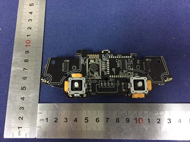
The main board. Each stick module (the white-topped squares) holds two potentiometers, one per axis. Photo: FCC filing 2AF9ST1D, internal photos.
The same pot also reaches only about 720 when pushed fully down, instead of 1023. That was the Tello’s throttle, the most-used axis, and the bottom of its track is worn.
What the bridge does about it:
- Centre: sampled at each connect, from the first still second. C1 + C2 re-samples.
- Range: each side of each axis is scaled to its own measured travel, so a pot that tops out at 720 still gives full output. Exact limit values (0 and 1023) are never learned as range, because on a worn pot they’re contact dropouts, not travel.
- Dead zone: 15%, radial, with the rest of the travel rescaled to full output.
- Dropouts:
--rail-timeout 2treats an axis stuck at its limit for 2 seconds as centred until it moves. It also cuts a deliberate full-stick hold after 2 seconds, so it’s off by default.
The hardware fixes, cheapest first (I haven’t done either yet):
- Contact cleaner. Open the shell, spray a plastic-safe electrical contact cleaner (DeoxIT D5 or similar, not WD-40) into the slot of each potentiometer, and work the stick in circles for 30 seconds. About 15 minutes; usually good for months.
- New stick modules. Potentiometer modules cost a few dollars and wear the same way again. Hall-effect modules (GuliKit, K-Silver JH16 and similar, in the common ALPS footprint) have no track to wear. Either way it’s 14 through-hole pins per module to desolder, and the height and pin spacing vary, so measure the T1d’s module first. About an hour.
Why not new firmware?
Section titled “Why not new firmware?”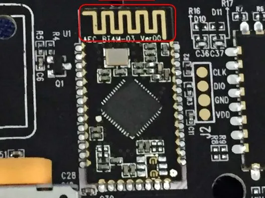
The BLE module and its debug pads. Photo: FCC filing 2AF9ST1D, internal photos.
The controller’s Device Information service reports a PnP ID of vendor 0x000D (Texas Instruments), product 0x0000, version 0x0110: the defaults of TI’s BLE stack sample code. So the module almost certainly holds a TI CC2540 or CC2541 (an 8051 core), and the CLK/DIO pads next to it are its 2-wire debug port. I couldn’t read the chip marking, so that’s a strong guess, not a fact.
Custom firmware would mean IAR’s 8051 compiler, TI’s BLE-Stack 1.4 and a CC Debugger on those pads, with no public source to start from. The T1s firmware is for a different board. The bridge gets the same result without any of that.
On Windows
Section titled “On Windows”People have written the same bridge with bleak and the ViGEmBus driver (install ViGEmBus only from Nefarius’s official v1.22.0 release):
- Isaac-dot-py/T1d-hack: one script, virtual Xbox 360 pad
- geonho99/GameSir-T1d_Driver_for_Windows: device picker and an
.exebuild - notblured/Gamesir-T1d-DS4: emulates a DualShock 4
Next idea: a USB dongle
Section titled “Next idea: a USB dongle”An ESP32-S3 can be the BLE side and show up on USB as an ordinary HID gamepad, so a Steam Deck, a TV box or any PC sees a wired controller with nothing to install. imbiribajr/GameSirT1d already has the T1d’s BLE side in ESP-IDF; the USB HID part is still to write. About AU$15 in parts.
Sources
Section titled “Sources”- FCC filing 2AF9ST1D: photos, user manual
- Protocol: dg-hub/gamesir-t1d-driver, ElishaAz’s gist, dronelab.dev, pors/gamesir_t1d
- “T1d is Tello-only”: DJI forum, Tello Pilots
Questions or comments? Discuss on Hacker News.
Change history
- : Every button now verified, stick clicks (L3/R3) and Home included. The pair button drops the connection, by design.
- : First published.